|
|
VSAAB
-- The Vintage SAAB Information Source! VSAAB Articles How To Rebuild Your Type III Brake Master Cylinder |
 |
|
|
VSAAB
-- The Vintage SAAB Information Source! VSAAB Articles How To Rebuild Your Type III Brake Master Cylinder |
|
(please click on the diagrams for a closer look)
All
1967 through 1974 Sonetts and 1964 through 1969 95s and 96s use what is
referred to as a type III, two-circuit brake master cylinder. Although
the master cylinder lid (5) differed on some models, the interior parts
remained the same. The master cylinder has two separate chambers. One
controls the right front and left rear wheel and the other the left
front and right rear wheel. The reason for this was so that the car
could be stopped in a straight line with a leaking master cylinder
chamber or broken brake line.
 A
poorly functioning brake master cylinder can show some of the following
symptoms; Spongy brake pedal due to worn primary or secondary cups (12)
(15) (21). Very firm brake pedal due to clogged bypass ports (3) (4)
(6)(7), resulting in brakes hanging up.
A
poorly functioning brake master cylinder can show some of the following
symptoms; Spongy brake pedal due to worn primary or secondary cups (12)
(15) (21). Very firm brake pedal due to clogged bypass ports (3) (4)
(6)(7), resulting in brakes hanging up.
NOTE:
the most common reason for brakes hanging up is clogged rubber brake
hoses, not brake master cylinder problems. And lastly, brake fluid loss
caused by a failing secondary cup (26).
Master cylinder rebuilding can be accomplished in two ways. You can send the cylinder out for re-sleeving and rebuild for about $175, or you can buy a rebuild kit from Saab for $22 and do it yourself. If after disassembly you find that the cylinder bore is deeply pitted, I recommend re-sleeving.
 White
Post Restorations, (540) 837-1140, One Old Car Drive, White Post, VA
22663 can do re-sleeving and rebuilding. Included in White Posts $175
fee is a full lifetime warranty.
White
Post Restorations, (540) 837-1140, One Old Car Drive, White Post, VA
22663 can do re-sleeving and rebuilding. Included in White Posts $175
fee is a full lifetime warranty.
Now
then, since most of you love a good challenge and would never pass up
the opportunity to save over $150, I have put together the following
"easy to follow" rebuilding instructions.
Before we begin I must
warn you. The only brake master cylinder parts that are available from
Saab are contained in their rebuild kit (#7836430). All other parts, not
to mention a complete new master cylinder, are no longer available. The
master cylinder contains a plethora of tiny spring-loaded pieces that
have been waiting for decades to go twanging across your garage floor.
You must be cautious and creative to curtail their quest for freedom.
Let's
begin.
1. Open the brake fluid
bleeder on the right rear wheel; pump the brake pedal until the fluid
stops running out. Repeat this procedure, one at a time, on the
remaining wheels.
Note:
clutch master cylinder removal will make the following steps much easier
as it blocks access to the brake master cylinder.
2.
Remove the rubber hose that goes into the master cylinder lid (5) if so
equipped.
3.
Loosen, but do not remove, the steel brake line fittings where they
screw into the banjo fittings (32). Disconnect the wires that go to the
brake light switch, unscrew switch.
4.
Remove the two banjo screws that secure the banjo fittings to the
cylinder body (33).
5.
Remove the two nuts that secure the cylinder to the firewall.
One is located in the engine compartment and the other in the passenger
compartment.
6.
Remove the master cylinder from the car. Remove the banjo fittings (32)
by loosening the brake line fittings the rest of the way (note the
positioning of the banjo fittings).
7.
Blow compressed air through the steel brake lines while opening one
brake fluid bleeder at a time.
8.
Clean out any dirt that is stuck in the threaded ends of the banjo
fittings. Reattach banjos to steel brake lines but do not fully tighten.
Tape the hole in the center of the banjos closed and tighten all
bleeders.
9.
Remove rubber boot (11), push down on spring retainer (30) and remove
spirolox circlip (29). The spring can be held in the compressed position
by clamping a large vise grip on the edge of the cylinders mounting
flange and the edge of the spring retainer. Separate the edge of the
spirolox circlip with a small screwdriver, and then spin off.
10.
Bend out the four tabs on the retaining plate (8) and remove.
11.
Remove circlip (28) exposing the white plastic guide bearing (27).
12.
Guide bearing removal: Before attempting to remove the guide bearing you
must clean away any dirt or rust that has collected in front of the
bearing. I used a Dremel tool equipped with a tiny wire wheel, but
sandpaper should suffice. Damaging the guide bearing is not an issue
since it is included in the rebuild kit. Damaging the now-discontinued
primary piston (10) should be your major concern. Wrap the piston with a
little electrical tape to provide some protection during the next steps.
Bearing removal can be accomplished in at least two ways.
Method
#1 - Drill four small holes at 90 degrees to one another through the
bearing face. Install four small screws into the holes. Make sure the
screws are small enough in diameter that they do not expand the bearing,
wedging it in the bore. Using a small pair of channel locks or pliers,
pull the bearing out by prying up on the screw heads alternately.
Method
#2 - as suggested by Bud Clark of J&B Imports: using the tip of a
soldering gun, melt the plastic bearing in several places and extract
the pieces. Bud said the bearing would give off some very toxic fumes so
a respirator should be worn.
13.
Remove the rubber secondary cup (26) with a small screwdriver, being
careful not to scratch the bore or primary piston. Remove the thin
washer (25) by tapping the cylinder on your workbench. Remove circlip
(24). Remove piston stop ring (thick washer) (23) by tapping the
cylinder on your workbench. Pull the piston assembly out of the bore.
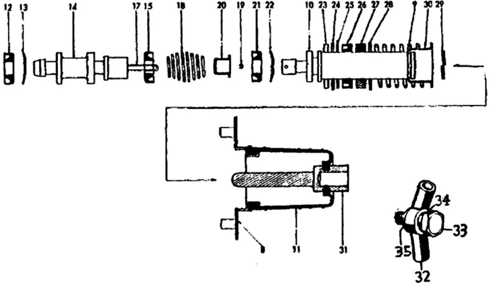 14.
Piston assembly rebuilding: Compress the spring holder (20) and spring
(18) to expose the retaining pin (19). Place a small nail between the
spring holder and piston (10) to hold the spring back while working on
the retaining pin. Using a suitable punch, tap the retaining pin out of
the cylinder just far enough to allow the clip (17) to be unhooked from
the retaining pin. Do not drive the pin out completely. This is one of
those moments when pieces are waiting to go flying all over the place.
While holding back the spring (18), separate the secondary piston from
the primary piston. Remove the three rubber cups (12) (15) (21 ) noting
their direction. Remove the two piston washers (13) (22). If the
retaining pin (19) is correctly positioned you can remove and replace
cup (21) and washer (13) over it. Clean all parts thoroughly with brake
fluid taking special care to clean out the small holes in the pistons.
Install new piston washer (13) and primary cup (12). Install secondary
cup (15) using the plastic cone shaped installation tool supplied with
the rebuild kit. Install piston washer (22) and primary cup (21). Slide
on the spring (9) and spring holder (20). While compressing the spring,
hook the end of the clip (17) on the retaining pin (19). Drive the pin
in flush with the primary piston.
14.
Piston assembly rebuilding: Compress the spring holder (20) and spring
(18) to expose the retaining pin (19). Place a small nail between the
spring holder and piston (10) to hold the spring back while working on
the retaining pin. Using a suitable punch, tap the retaining pin out of
the cylinder just far enough to allow the clip (17) to be unhooked from
the retaining pin. Do not drive the pin out completely. This is one of
those moments when pieces are waiting to go flying all over the place.
While holding back the spring (18), separate the secondary piston from
the primary piston. Remove the three rubber cups (12) (15) (21 ) noting
their direction. Remove the two piston washers (13) (22). If the
retaining pin (19) is correctly positioned you can remove and replace
cup (21) and washer (13) over it. Clean all parts thoroughly with brake
fluid taking special care to clean out the small holes in the pistons.
Install new piston washer (13) and primary cup (12). Install secondary
cup (15) using the plastic cone shaped installation tool supplied with
the rebuild kit. Install piston washer (22) and primary cup (21). Slide
on the spring (9) and spring holder (20). While compressing the spring,
hook the end of the clip (17) on the retaining pin (19). Drive the pin
in flush with the primary piston.
15.
Remove the six bolts that secure the lid (5) to the cylinder body.
Remove the gasket and clean out the lid and fluid chambers.
16.
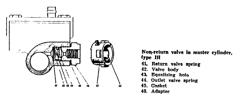
Remove adapters (46) exposing the valve bodies (42). Knock out the valve
bodies and remove the return valve springs (41). Clean out the valve
bodies taking care not to lose the outlet valve springs (44).
17.
Cylinder bore honing: The cylinder has a 3/4 inch inside diameter.
Snap-On tools makes a two stone hone that will do the job nicely. Do not
try using a three stone hone, as it will not fit inside the bore. Using
a variable speed drill at low speed with plenty of brake fluid as a
lubricant, run the hone the full length of the bore. Run the hone long
enough to smooth out the bore, do not over hone.
18.
Clean out the tiny bypass ports (3) (6) with a small wire (I used a
guitar string). Thoroughly flush out the cylinder bore with brake fluid.
19.
Secure the lid and gasket with six bolts. Install the return valve
spring (41), valve body (42), copper gasket (45) and adapter (46).
20.
Coat the rebuilt piston assembly with brake fluid and press inside the
cylinder bore.
21.
Drop in the piston stop ring (thick washer)(23). Install circlip (24).
Drop in thin washer (25). Press in new secondary cup (26) with flat side
facing out. Press in new guide bearing (27), install circlip (28). Put
on retaining plate (8), bend over tabs. Install spring (9) and spring
retainer (30). Compress spring with retainer and spin spirolox circlip
(29) on to primary piston (10). Install rubber boot (11).
22.
Apply grease to push rod (31). Reattach master cylinder to firewall.
Fasten master cylinder to banjo fittings with banjo screws (33). Don't
forget copper washers (34) (35). Retighten steel brake lines to banjo
fittings, attach brake light switch. Connect rubber hose to cylinder lid
if so equipped. Fill system with brake fluid and bleed.
Just
before writing this article I rebuilt three Sonett brake master
cylinders that were lying in my shed for several years. During the
rebuilds I discovered that condensation was attacking the cylinder bores
while they sat in storage. Had I waited another couple of years the
cylinders would have required resleeving.
The
most important part of the rebuild is protecting the primary piston from
scratches while removing the dreaded plastic guide bearing. If you have
patience and take safeguards to catch the inevitable spring-loaded
projectiles, this job is not as difficult as it sounds.
Bruce Turk, 6/01
So, what do you think of this? Send us your thoughts and comments by clicking HERE!
All product and trade names
mentioned on this site are the trademarks of their respective companies.
�VSAAB, 1998-2001 All rights
reserved. VSAAB is not affiliated with SAAB Cars USA or SAAB Automobile.
"VSAAB" is a trademark of the San Diego SAAB Owner's Group, San
Diego, California USA.
All information here is presented as personal opinion. Ask, think, do.
Last modified:
January 10, 2023